How I made a physical part I had no real business being able to make.
There is a cat flap-shaped hole in my door, and I wanted to run two 100 mm air ducts through it. This is how I got a printable part for that, without opening a CAD program, and why it changed how I think about what AI is actually useful for.
The problem nobody sells a part for
The cat flap left the usual opening: a tombstone shape, flat at the bottom with a domed top, roughly 150 mm wide and 120 mm tall.
I needed to pass two 100 mm ducts through it, from one side of the door to the other. The part had to transition from two round ducts into that flap-shaped hole, then back out to round duct on the far side. And the two airflows had to stay separate the whole way through.
That part does not exist. It is bespoke geometry: a twin-channel transition from two circles to a tombstone profile, with a divider down the middle to stop the streams mixing.
I can segment a network, automate half the house, and wrangle a CI pipeline before breakfast. But lofting that in Fusion is beyond my patience and skill. Normally this is where the idea quietly dies and I prop the door open instead.
Describing a shape, badly
Instead, I opened a chat, roughly described what I wanted, gave it the two dimensions, and showed it a photo of the flap.
The first thing that struck me was that it asked the two questions that mattered, the same ones a fabricator would ask:
Do the two airflows need to stay separate, or can they merge? Separate, because it is supply and extract. Should the round ends be spigots the duct pushes over, or sockets it pushes into? Spigots.
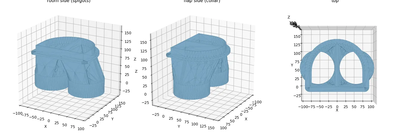
Out came a parametric model, written in CadQuery, a Python library that builds CAD geometry in code, and an STL ready to slice.
It had also worked out that each half of the tombstone was almost exactly the same area as one 100 mm duct. So the airflow split would be balanced rather than throttled. I had not asked it to think about that. It just did.
The bit that surprised me: it is parametric, and it checks its own work
This was not a static mesh I had to accept or reject. It was a script, with the values I might want to change sitting right at the top:
W        = 150.0   # flap aperture width
H        = 120.0   # flap aperture height
WALL     = 3.0     # wall thickness
DUCT_OD  = 100.0   # spigot outer diameter (duct pushes over this)
Wrong by 4 mm? Change a number, re-run it, and get a new part. The whole thing is driven by the geometry of my hole, not by a guess at a generic one.
It also rendered preview images of each version and inspected them. On the first try, it spotted that the arch was bulging to the wrong side of the divider, twisting the model into nonsense. It fixed that before I would have noticed.
The transition itself is a ruled loft between a circle and half a tombstone:
loft = Solid.makeLoft([
    circle_wire,            # the round duct end
    half_tombstone_wire,    # half the flap profile, split by the divider
], ruled=True)
I could not have written that. I did not have to.
The human very much stays in the loop
This is the bit I would want people to take away, because it is where the hype usually goes too far.
Before I committed about 370 g of filament to the full part, it suggested, and I asked for, a fit gauge: a thin slice of just the profile, to push into the real hole and check the size and arch curve. It printed in under an hour. The fit was spot on, which meant the expensive print should fit too.
It then wanted to design a proper joint between the two halves: bolts through the flange, telescoping collars, a gasket. I said I would use duct tape. It accepted that, though it fairly pointed out that tape would clamp the outside but would not seal the divider in the middle. A scrap of foam would do that.
Duct tape on a duct. I can live with the thematic consistency.
Then the gauge broke. The thin collar wall snapped off the flange at the sharp right angle where they meet, a classic weak point in a print.
I described this about as badly as possible: “where the inner bit meets the wider bit at a 90-degree angle, it broke.”
It understood exactly what I meant. It added an internal fillet that thickened the joint on the inside, so the join got stronger without changing the outer size. The good fit I had already checked stayed untouched.
Why this changed what I thought AI was for
I expected AI to help me write, summarise, and move code around. I did not expect to hand it a vague shape from inside my head and get back a watertight, parametric, printable object that now does a real job in my house.
The loop is the thing: describe → generate → print → test → feed back → regenerate.
It is pair programming, except the thing you make is a physical object you can hold, push into a hole, and snap in half.
And it is not magic. It is not autonomous. It cannot measure my door. It cannot run the printer. It cannot feel the part flex and give way in my hands.
I did all of that. The judgement calls stayed with me: tape versus bolts, what counts as good enough, and when to stop.
What it removed was the one step that always killed these projects before: turning intent into manufacturable geometry. That step used to be a wall. Now it is a conversation.
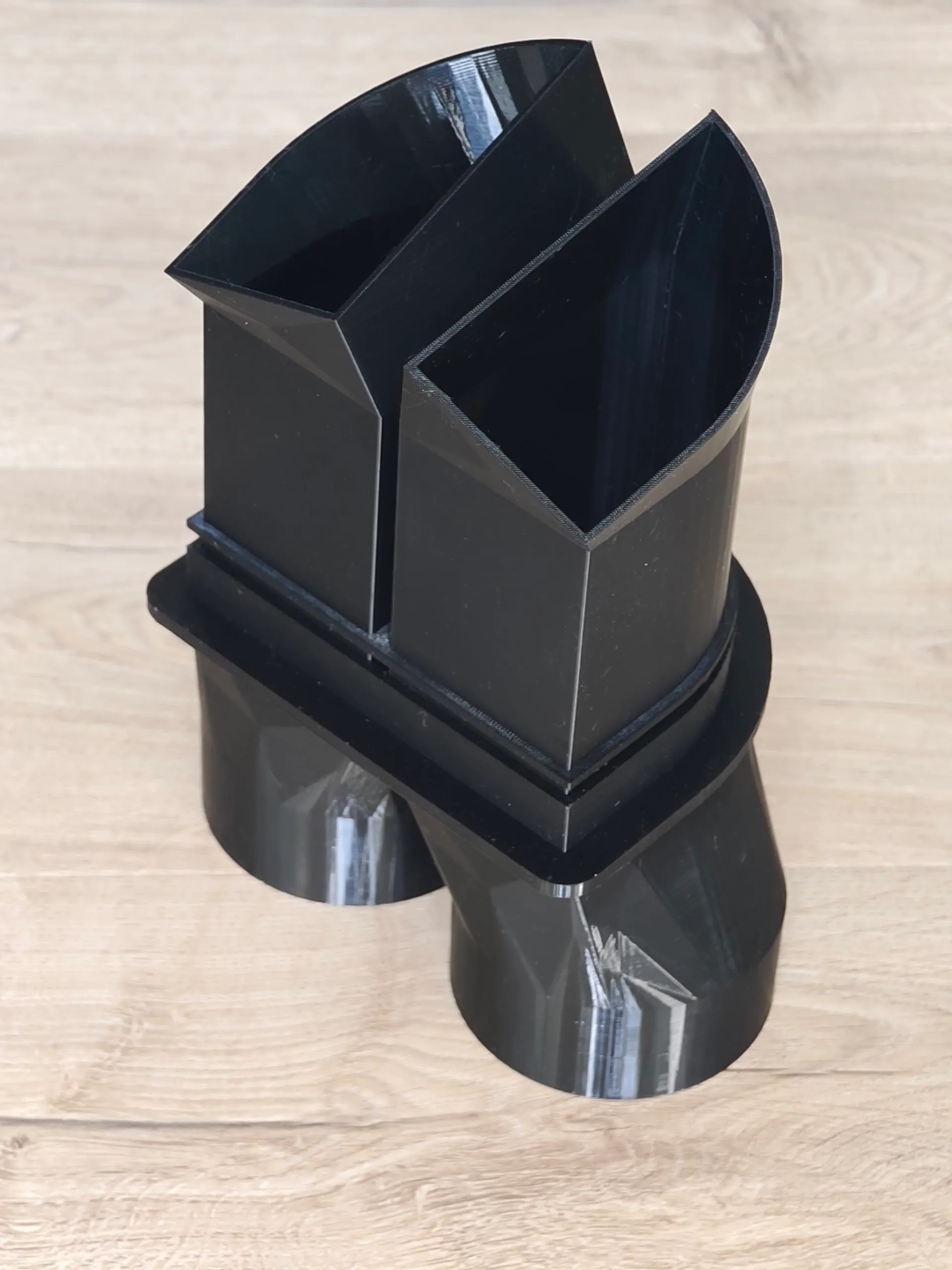
The part is on the printer now. Two copies, taped in the middle, foam on the divider, ducts pushed over the spigots.
It is not elegant. It works. And a week ago I would have told you it was something I simply could not make.
Built with CadQuery and a 3D printer. The model is fully parametric, so if your flap is a different size, it is a two-number change and a re-run away.